Example Design Review Documents
These are pre-generated design review documents showing the full analysis output. Each report contains 10,000+ words of technical DFT analysis, EMC checks, connector pinouts, and testpoint coverage documentation:
- FPGA1394V3 Design Review — IEEE 1394 FireWire interface with Xilinx XC7Z020 FPGA, BSDL boundary scan analysis, JTAG chain validation
- MB1191 Design Review — STM32 Nucleo-144 development board with ARM Cortex-M processor
- TIDA-050036 Design Review — Texas Instruments industrial base board reference design
Samples You Can Try
- FPGA1394V3.zip — IEEE 1394 FireWire interface with Xilinx FPGA, multi-sheet hierarchy
- MB1191.zip — STM32 Nucleo-144 development board (ST Microelectronics)
- TIDA-050036.zip — Texas Instruments industrial base board reference design
Download any sample, upload it on the Submit page, and receive a full analysis report.
Sample Report Output
Tomachie generates an interactive HTML report with navigable sections. Here's what you'll receive:
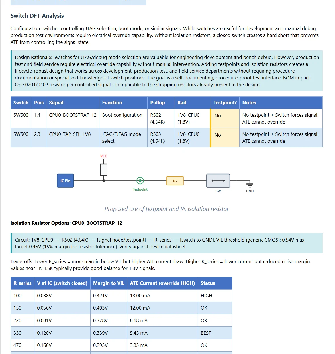
Switch DFT analysis — identifies configuration switches lacking test override capability, calculates isolation resistor values for ATE compatibility.
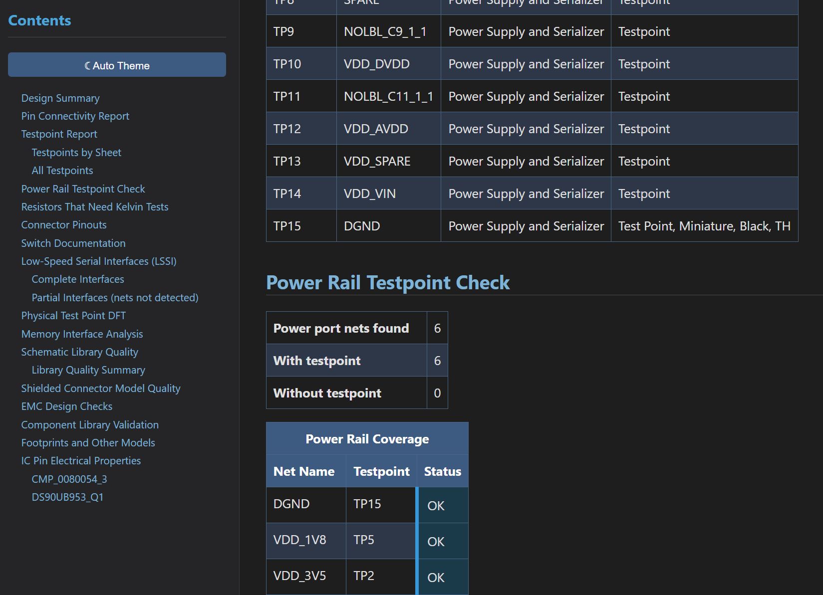
Testpoint inventory with power rail coverage analysis — every power net checked for test access.
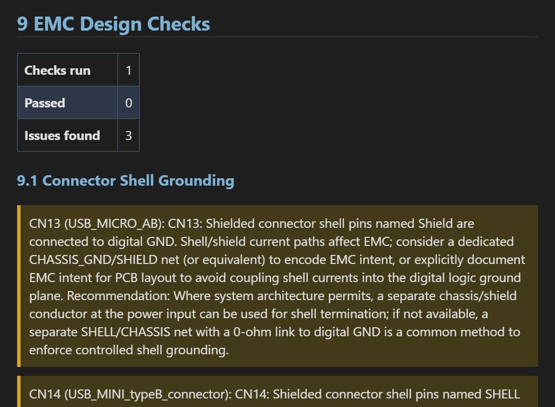
EMC design checks, component library validation, and footprint/model audit — all in one report.
The left navigation panel lets you jump directly to any section. Reports include Design Summary, Pin Connectivity, Memory Interfaces, Serial Interfaces, Connector Pinouts, DFT Analysis, Library Quality grades, and more.
Current Focus: Digital and mixed-signal designs — processors, FPGAs, memory interfaces, serial buses, and testability analysis. Analog-specific checks (power supply loop stability, filter analysis) are on the roadmap.
What to Upload
ZIP your schematic files and upload. Here's what we need:
Schematic files (required)
Altium .SchDoc or KiCad .kicad_sch files — include all sheets referenced by the hierarchy.
Project files (recommended)
Altium: .PrjPcb, .PrjPcbStructure, .PrjPcbVariants. KiCad: .kicad_pro. These tell us the hierarchy and top-level sheet. Without them, you'll need to specify the top sheet name, or we'll assume a flat design.
*.bsdl files (optional)
Boundary Scan Description Language files. These files use IEEE 1149.1-2013 to describe the test capability of the digital ICs. If provided, Tomachie will analyze the correctness, compliance and Design-for-Test of your design.
Tip: When requesting schematics from a designer or contractor, ask for the project files (.PrjPcb or .kicad_pro) along with the schematic files. Many designers forget to include them.